Minolta Hi-Matic F: Difference between revisions
mNo edit summary |
No edit summary |
||
| (6 intermediate revisions by the same user not shown) | |||
| Line 1: | Line 1: | ||
=== General notes === | === General notes === | ||
There are at least two versions of this camera | There are at least two versions of this camera: | ||
* Version A has a flash sync socket on the side of the body and a pressed steel rewind crank ratchet plate | |||
* Version B has no flash sync socket (apart from the hot shoe) and a flat steel rewind crank ratchet plate with a plastic spacer underneath it | |||
There's no meter movement - an IC converts the light level from the LDR into a shutter delay via a small solenoid. | There's no meter movement - an IC converts the light level from the LDR into a shutter delay via a small solenoid. | ||
| Line 9: | Line 12: | ||
=== Disassembly === | === Disassembly === | ||
As usual for cameras of this type, you need to take the charge lever and the rewind crank off to remove the top cover. The rewind crank screws off by turning it anticlockwise. Once the covers and leatherettes are off, the baseplate assembly comes off in one piece by disconnecting all the wires (2 at the bottom need to be unfolded from hiding spots and desoldered, some of the wires at the top are connected to contacts that can be demounted by one screw or an e-clip) and removing the 4 screws. | As usual for cameras of this type, you need to take the charge lever and the rewind crank off to remove the top cover. The rewind crank screws off by turning it anticlockwise. More unusually, you also need to remove the flash hot-shoe. The serial number is engraved into a thin metal cover which unclips and slides off, revealing 4 screws that need to be removed. No need to desolder the contact or thread it through the hole. | ||
The metal bracket underneath the hot shoe detaches by removing 2 more screws and comes off. | |||
[[File:Hot shoe bracket.jpg|none|thumb|Hot-shoe bracket with 2 screws to remove]] | |||
The viewfinder can be demounted via 3 screws, no need to disconnect anything else. The only thing that it interacts with is a push rod for the focus which is underneath it. | |||
[[File:Rangefinder.jpg|none|thumb|Screws to remove rangefinder (arrowed)]] | |||
Once the covers and leatherettes are off, the baseplate assembly comes off in one piece by disconnecting all the wires (2 at the bottom need to be unfolded from hiding spots and desoldered, some of the wires at the top are connected to contacts that can be demounted by one screw or an e-clip) and removing the 4 screws. | |||
The frame counter assembly comes off easily by removing 2 diagonally-opposite screws. | |||
If you need to remove the ratchet gear from the charge axle, you need to press out a pin. You shouldn't need to do this unless corrosion gets in the way of getting these parts off the camera. Similarly, the small gear with a spring wrapped around it at the bottom of the take-up spool gear (this is a one-way turning system) has a pin holding it together as well, underneath the spring. | |||
To access the inside of the lens at the front, start with unscrewing the notched silver ring just inside the filter thread. | |||
The baseplate is mostly mechanical with a traditional clockwork self-timer. There is a timing geartrain for the shutter as well as a solenoid which delays something in the shutter timing in some unknown manner. | |||
[[File:Shutter geartrain.jpg|thumb|Arrangement of shutter timing gears on the back of the baseplate.|none]]There is a plastic riser implanted in the baseplate, underneath the right-hand end of the shutter charging shuttle (bottom right in the above image). This is pressed into the plate - don't remove it unless you have to. It's brittle and may not survive being re-inserted. If you have to re-insert it, then you will definitely need to taper out the top of the hole at little bit so that the plastic will go back in. Otherwise it'll simply refuse to fit, and break. | [[File:Shutter geartrain.jpg|thumb|Arrangement of shutter timing gears on the back of the baseplate.|none]]There is a plastic riser implanted in the baseplate, underneath the right-hand end of the shutter charging shuttle (bottom right in the above image). This is pressed into the plate - don't remove it unless you have to. It's brittle and may not survive being re-inserted. If you have to re-insert it, then you will definitely need to taper out the top of the hole at little bit so that the plastic will go back in. Otherwise it'll simply refuse to fit, and break. | ||
A note about the small spring that rests against one of the shutter charge shuttle is mounted over: when this spring is in its correct position, it can be hard to get the gears to sit still while you put the PCB back on top, and they have a tendency to jump out of position. You CAN move the tip of the spring back to the post to the right of it, which takes a lot of the spring pressure off | A note about the small spring that rests against one of the shutter charge shuttle is mounted over: when this spring is in its correct position, it can be hard to get the gears to sit still while you put the PCB back on top, and they have a tendency to jump out of position. You CAN move the tip of the spring back to the post to the right of it, which takes a lot of the spring pressure off it. Then once the PCB is back on, you can access the end of the spring with needle-nose pliers from the edge of the sandwich to move it back to the correct place again. | ||
[[File:Shutter-blades.jpg|none|thumb|Arrangement of shutter/aperture blades ]] | |||
There are only two blades for a combined shutter and aperture. | |||
Latest revision as of 11:51, 8 May 2025
General notes
There are at least two versions of this camera:
- Version A has a flash sync socket on the side of the body and a pressed steel rewind crank ratchet plate
- Version B has no flash sync socket (apart from the hot shoe) and a flat steel rewind crank ratchet plate with a plastic spacer underneath it
There's no meter movement - an IC converts the light level from the LDR into a shutter delay via a small solenoid.
There's one left-hand threaded screw. It's the main wind-on lever gear at the right side of the camera when the bottom cover is off, with a thin flat-head drive.
Corrosion of steel contacts seems to be a common problem for the two examples I've seen so far.
Disassembly
As usual for cameras of this type, you need to take the charge lever and the rewind crank off to remove the top cover. The rewind crank screws off by turning it anticlockwise. More unusually, you also need to remove the flash hot-shoe. The serial number is engraved into a thin metal cover which unclips and slides off, revealing 4 screws that need to be removed. No need to desolder the contact or thread it through the hole.
The metal bracket underneath the hot shoe detaches by removing 2 more screws and comes off.
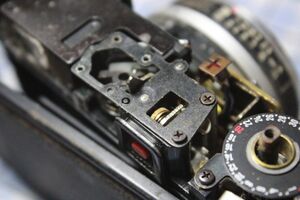
The viewfinder can be demounted via 3 screws, no need to disconnect anything else. The only thing that it interacts with is a push rod for the focus which is underneath it.
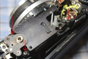
Once the covers and leatherettes are off, the baseplate assembly comes off in one piece by disconnecting all the wires (2 at the bottom need to be unfolded from hiding spots and desoldered, some of the wires at the top are connected to contacts that can be demounted by one screw or an e-clip) and removing the 4 screws.
The frame counter assembly comes off easily by removing 2 diagonally-opposite screws.
If you need to remove the ratchet gear from the charge axle, you need to press out a pin. You shouldn't need to do this unless corrosion gets in the way of getting these parts off the camera. Similarly, the small gear with a spring wrapped around it at the bottom of the take-up spool gear (this is a one-way turning system) has a pin holding it together as well, underneath the spring.
To access the inside of the lens at the front, start with unscrewing the notched silver ring just inside the filter thread.
The baseplate is mostly mechanical with a traditional clockwork self-timer. There is a timing geartrain for the shutter as well as a solenoid which delays something in the shutter timing in some unknown manner.
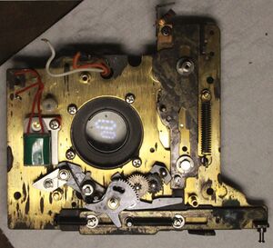
There is a plastic riser implanted in the baseplate, underneath the right-hand end of the shutter charging shuttle (bottom right in the above image). This is pressed into the plate - don't remove it unless you have to. It's brittle and may not survive being re-inserted. If you have to re-insert it, then you will definitely need to taper out the top of the hole at little bit so that the plastic will go back in. Otherwise it'll simply refuse to fit, and break.
A note about the small spring that rests against one of the shutter charge shuttle is mounted over: when this spring is in its correct position, it can be hard to get the gears to sit still while you put the PCB back on top, and they have a tendency to jump out of position. You CAN move the tip of the spring back to the post to the right of it, which takes a lot of the spring pressure off it. Then once the PCB is back on, you can access the end of the spring with needle-nose pliers from the edge of the sandwich to move it back to the correct place again.
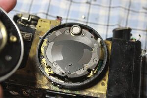
There are only two blades for a combined shutter and aperture.
